English
  English
 русский
 日本語
日本語 Español
 中文简体
中文简体
Heat tracing for oil storage tanks is an electric surface heating method that keeps stored hydrocarbons above their pour point and at the required process temperature. Heating cables are fixed to the tank shell or floor, and a thermostat regulates their operation so that crude oil, heavy fuel oil, bitumen, and chemical products remain fluid and pumpable even in severe winter conditions. Once the contents of a tank cool and congeal, reheating is slow, expensive, and disruptive; the purpose of a tank heating system is to prevent that scenario entirely.
This guide explains what tank heat tracing is, why tanks need it, which cable technologies to compare, how to approach the design, and what control, installation, and maintenance details determine long-term reliability.
Content
What Is Heat Tracing for Oil Storage Tanks?
Heat tracing is a surface heating technique that maintains the temperature of the stored product rather than quickly raising it from cold. The tank is insulated first, and heating cables wrapped around or laid over the tank shell compensate for standby heat loss through the wall, roof, and bottom. This is why accurate sizing and stable temperature control matter more than raw power.
A complete oil storage tank heat tracing system consists of three parts:
- Heating cables, which generate the heat along the tank surface;
- Control and monitoring equipment, including thermostats, temperature sensors, and alarm devices;
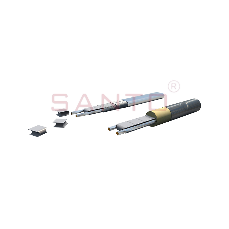
- Mechanical accessories such as foil tape, cable clips, thermal insulation, and weatherproof junction boxes.
Why Oil Storage Tanks Need Heat Tracing
Oil storage tanks need heat tracing because most hydrocarbons are not pumpable at ambient temperature: viscosity climbs as temperature falls, and pour-point solidification stops operations completely. Heat tracing is installed for operational, financial, and safety reasons combined.
- Viscosity control. Most heavy products can only be pumped at 50–70 °C. Below that, discharge pumps cavitate and flow rates collapse.
- Pour-point protection. Waxy crude and residual fuel can solidify inside the tank if the temperature drops below the pour point. Recovery then requires steam lancing, hot-oil circulation, or even tank entry.
- Moisture handling. Condensation inside a tank can freeze and block suction lines, and water at the tank bottom accelerates corrosion.
- Process reliability. A consistent feed temperature keeps downstream heaters, separators, and burners running within their design envelope.
- Structural safety. Repeated cooling and reheating, or buoyancy forces caused by a solidified surface layer, can damage tank walls and mixer supports.
Calculate the cost of one unexpected tank outage once, and the budget for a properly engineered heat tracing system looks very small in comparison.
Heat Tracing Technologies for Oil Storage Tanks
The right technology for a storage tank matches the maintain temperature, tank size, and site area classification. The four systems most commonly applied to oil storage tanks are self-regulating, constant wattage, mineral insulated, and skin-effect tracing.
| Technology | Output behaviour | Best suited for | Typical maintain temperature |
|---|---|---|---|
| Self-regulating | Power output falls as temperature rises | Small and medium tanks, retrofits, field-cut installation | 65–120 °C by series |
| Constant wattage | Stable output per metre at rated voltage | Large tanks, uniform heat, faster heat-up | 150–260 °C |
| Mineral insulated (MI) | High fixed output, metal sheath | High-temperature products, corrosive locations | Up to 400–600 °C |
| Skin-effect (SECT) | High power over long distances | Very large tanks and long transfer piping | System-dependent |
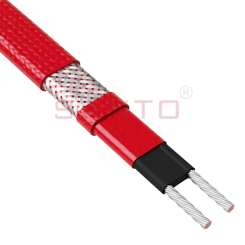
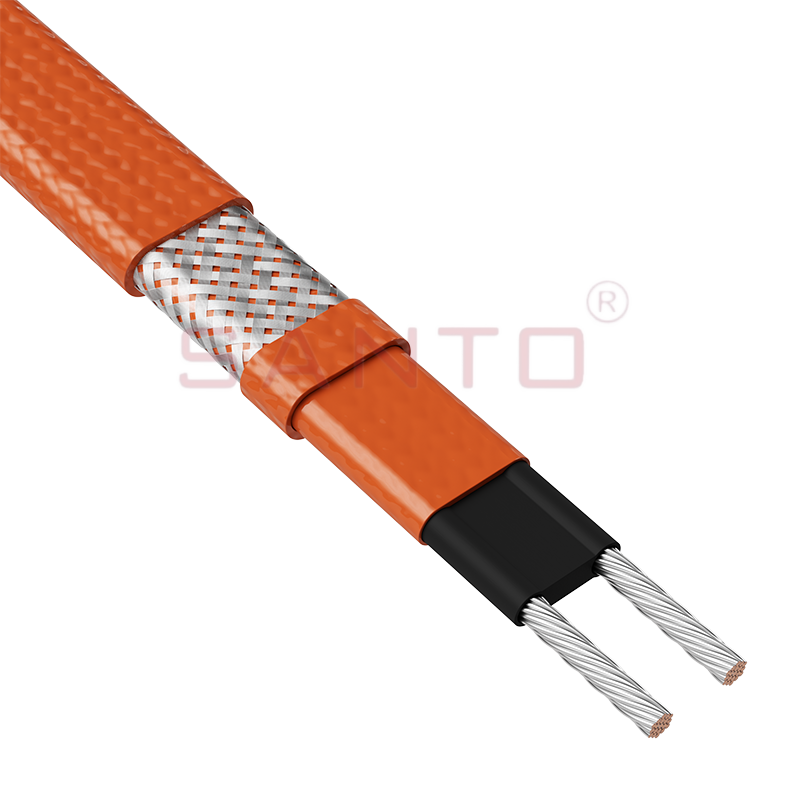
For most above-ground tanks, self-regulating cable is the standard starting point. It can be cut and terminated on site, adjusts its own output along the tank wall, and cannot overheat locally where brackets or pipe supports change the heat loss pattern.
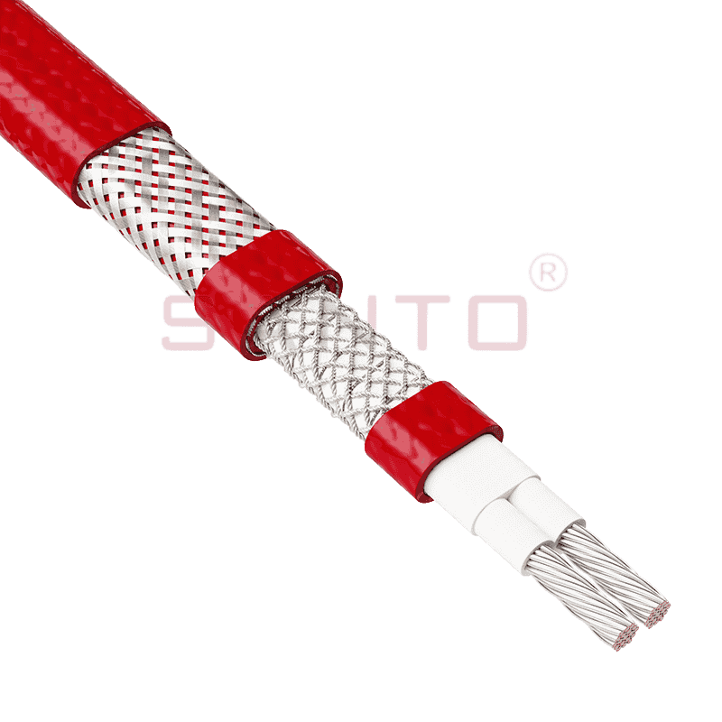
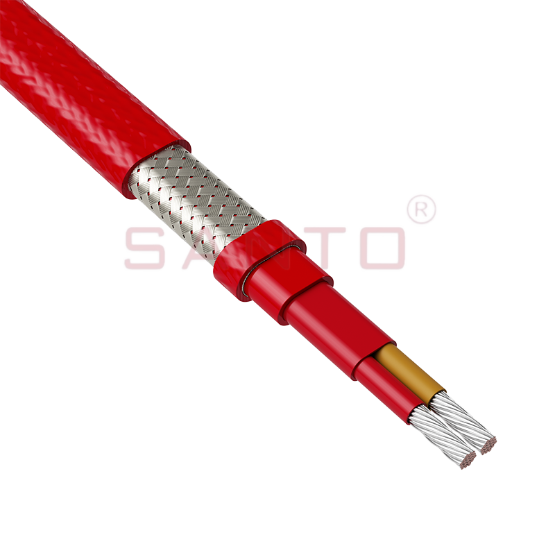
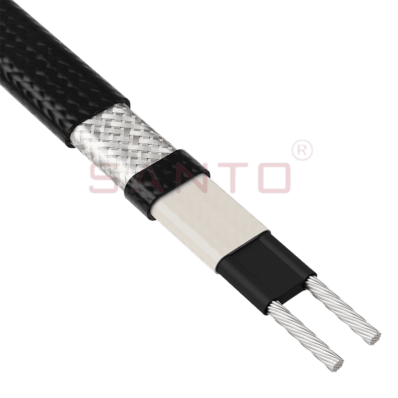 UFA Self-Regulating Heating Cable for Tank InsulationThis self-regulating cable is cut to length on site, adjusts output along the tank wall, and prevents local overheating. It offers polyolefin or fluoropolymer jackets and hazardous-area approvals.View Product →
The UFA series is a representative self-regulating heating cable for tank and vessel insulation. Before you finalize the specification, check how self-regulating heating cables perform in industrial tank insulation.
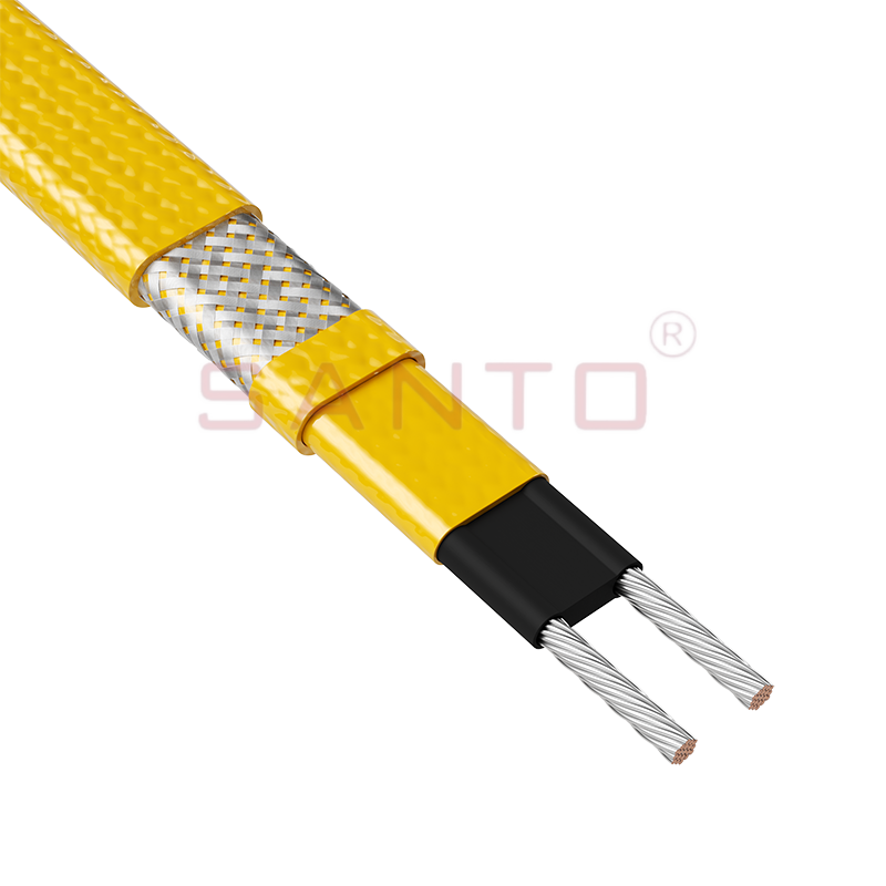
For large tanks that need uniform output at a higher maintain temperature, constant wattage cable is usually the better fit.
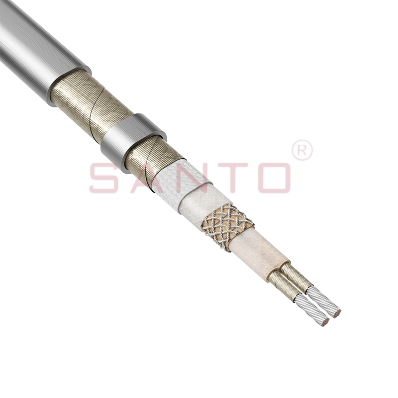
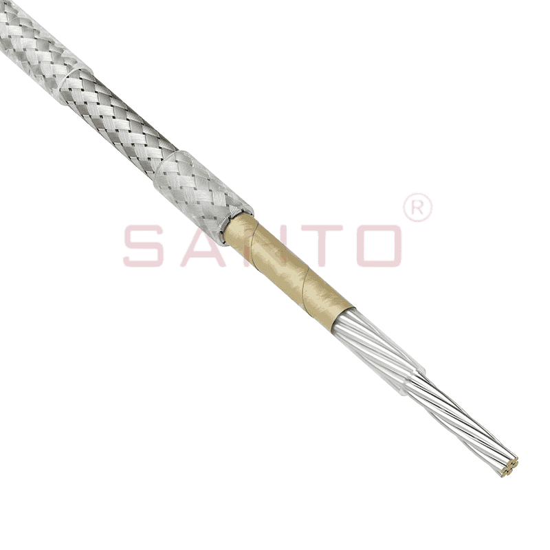
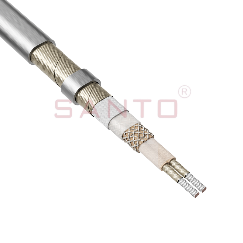 SANTO AMM Constant Wattage Heating Cable for High TemperaturesA constant power heat tracing wire for industrial pipelines and equipment, capable of maintaining temperatures up to 400°C. Suitable for high power output and high exposure environments, with hazardous-area certifications.View Product →
The Santo-AMM series belongs to this family and is intended for industrial heat tracing where the target temperature exceeds the practical limit of self-regulating designs.
Key Design Considerations
Tank heat tracing succeeds or fails on the heat loss calculation, not on the catalogue wattage of the cable. The governing number is the steady-state heat loss at the lowest ambient temperature for the site, converted into cable length, circuit spacing, and control setpoint.
| Design parameter | Why it matters | Typical guidance |
|---|---|---|
| Maintain temperature | Sets the required heat input and cable class | 50–60 °C for heavy fuel oil; 5–10 °C above the pour point for waxy crude |
| Minimum ambient temperature | Defines the worst-case heat loss | Use the local winter design temperature, for example −20 °C to −40 °C |
| Tank surface area | Determines total cable length and heat demand | Include shell, roof, and bottom heat loss where the floor is heated |
| Insulation type and thickness | Reduces heat loss and running cost | 50–100 mm mineral wool or polyurethane is common on heated tanks |
| Cable spacing and fixing | Guarantees even surface temperature | Usually 150–300 mm, confirmed against the cable output per metre |
Never size a tank system without the product pour point, the maximum permissible skin temperature of the tank wall, and the design ambient condition. These three values determine whether a self-regulating cable, a constant wattage cable, or a mineral insulated system is technically allowed at all.
For tanks located in Zone 1 or Zone 2 hazardous areas, both the heating cable and the temperature controller must match the area classification, and the maximum surface temperature of the cable must remain below the ignition temperature of the stored product and any flammable atmosphere around the tank.
Temperature Control and System Components
A tank heat tracing system is only as reliable as its temperature control. The thermostat should sense the tank wall or the product temperature, not the air temperature inside the tank, and the controller setpoint should be locked against unauthorized changes.
The main components of a control and distribution package are:
- A surface-sensing or immersion thermostat suitable for the zone;
- An intelligent controller with digital display and alarm output where monitoring is required;
- Weatherproof or explosion-proof junction boxes, power connection kits, and tail-end kits;
- A high-limit controller or high-temperature alarm where the tank wall temperature is restricted.
For hazardous-area tanks, an explosion-proof controller is mandatory rather than optional.
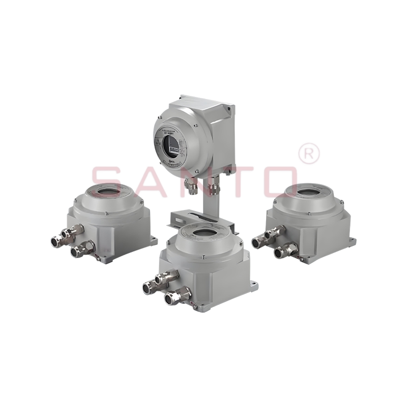 HDBK-WK Series Intelligent Explosion-Proof Temperature ControllerReplaces mechanical thermostats in electric tracing, offering precise control plus current protection, phase-loss warning, and leakage monitoring. Certified for hazardous areas, combining display and alarm in one unit.View Product →
The HDBK-WK series intelligent explosion-proof temperature controller is designed for this duty, combining temperature control, local display, and alarm functions in a single certified enclosure.
Installation and Maintenance Essentials
Installation quality has as much influence on system life as the cables themselves, and the same is true of a disciplined maintenance routine.
- Clean the tank surface and remove rust, scale, and oil before fixing the cable.
- Install the cable at the design spacing using approved clips or foil tape; avoid slack loops and overlapping runs.
- Keep the thermal insulation continuous and weatherproof; wet insulation increases heat loss and shortens cable life.
- Verify power supply voltage and circuit current before energizing, and check the cable's minimum installation temperature in cold weather.
- Record circuit drawings, joint locations, and thermostat setpoints in the maintenance file.
- Carry out insulation resistance and continuity tests after installation and during each annual inspection.
Frequently Asked Questions
Which heating cable is best for an oil storage tank?
For most tanks, a self-regulating cable is the best choice because it is safe to cut on site, adapts its power output to local temperature, and cannot overheat where pipes or supports cause variations in heat loss. For very large tanks with a high maintain temperature, constant wattage or mineral insulated systems may be more appropriate.
What temperature should an oil storage tank be kept at?
It depends on the product. Heavy fuel oil is usually kept at 50–60 °C, waxy crude at slightly above its pour point, and bitumen at the tank discharge temperature required for pumping. Always base the setpoint on the operating requirements and the cable's maximum maintenance temperature.
Do oil storage tanks need explosion-proof heat tracing components?
If the tank operates in a Zone 1 or Zone 2 hazardous area, the heating cable, thermostat, and junction boxes must all comply with the area classification. Otherwise, the maximum surface temperature could exceed the ignition temperature of the surrounding atmosphere and turn the tank into an ignition source.
How do I know if my tank heat tracing is working correctly?
Check the supply voltage, measure the circuit current and compare it with the calculated value, verify the thermostat setpoint with a contact thermometer, and carry out an insulation resistance test. These checks should be performed annually and after any work on the insulation or tank surface.
Can self-regulating cables be overlapped on a storage tank?
In principle, self-regulating cables can be overlapped without burning out because their output decreases as temperature rises. However, an overlap creates a concentrated hot area on the tank surface. Avoid overlaps in the design, and always check the cable's minimum installation temperature when laying in cold weather.
Heat tracing for an oil storage tank is a mission-critical investment, not an accessory. Define the maintain temperature, calculate the heat loss honestly at the worst ambient condition, choose a cable technology that matches the tank size and area classification, and control it with a thermostat that fits the zone. Follow these steps, and the tank will discharge reliably through winters that would otherwise shut it down.